Control Shaft Guide Pin

'46 CJ-2A column shift


This part in not identified by any diagram, photo or part number in any WIllys manual I've seen.

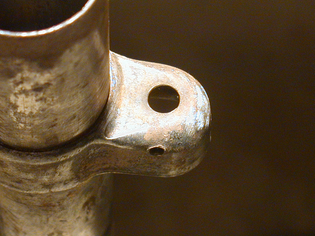
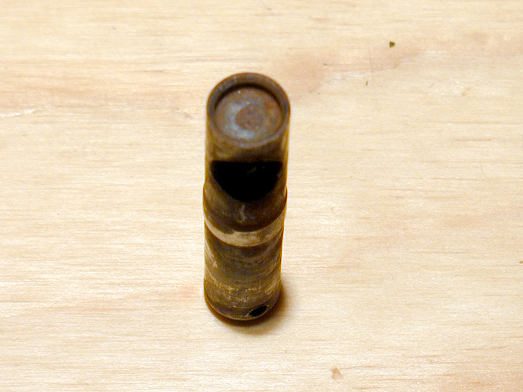
Detail and dimension are in the Mechanical Drawing of this part: Guide Pin (PDF), 36 KB

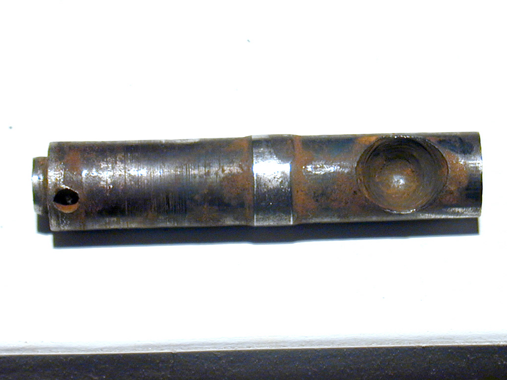
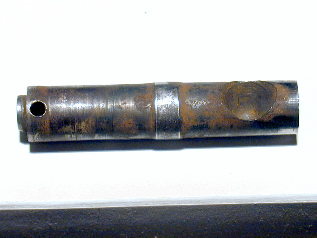
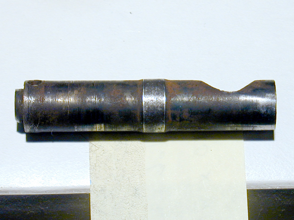
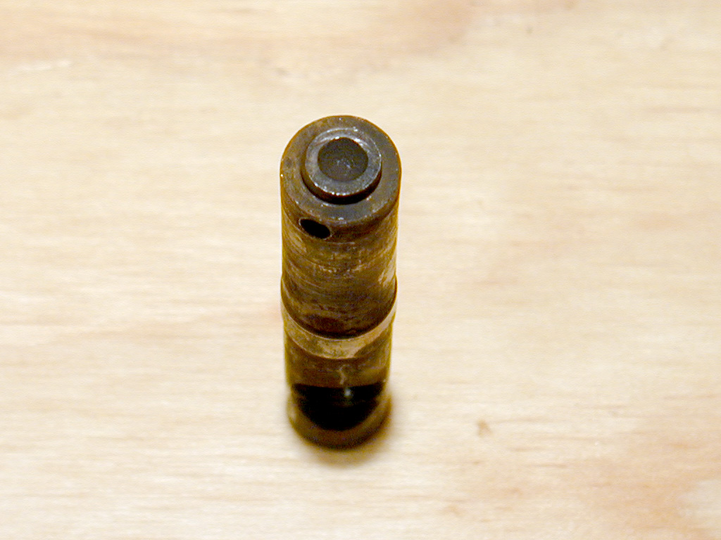
*** A WORD OF CAUTION (if you're planning to fabricate this pin): I am convinced that either: A) this pin was machined incorrectly, or B) is not Willys original. I can't say which. See the photos in the assembly pages.

Comments, suggestion and corrections are welcome.

Pictures below all link to higer resolution images (1024 x 768) for more detail.


This photo taken as nearly aligned with the shift lever bore axis as possible.

The shift lever bore is conical in shape with rounded apex.

Note that the spring pin hole (at left end) is not parallel to the shift lever bore.

This photo taken as nearly aligned with the spring pin hole as possible.

Note that the shift lever bore (at right) has rotated upwards from the previous picture.

See how this affects alighnment on the Assembly pages

 
Side view showing shift lever bore side scoop on the pin.
 

The upper end of the guide pin.

The raised nub fits into the hole on the coluimn bracket (shown below).

 
The guide pin hole, and the spring pin hole, in the column bracket.
 
The lower end of the guide pin, showing the recess for the bias spring.